Configuring attribute permissions and import settings
In the Project Environment dialog, in [project] > Configuration > Diagram > Integration settings, the project administrator can configure the interface between Plant Modeller and P&ID in regard to which application can modify integration attributes and how diagram (EPD) objects are imported from XML files.
Attribute permissions tab
In the Diagram – Plant Modeller integration settings dialog, on the Attribute permissions tab, you can specify whether applications are permitted to modify the values of COS attributes that are used in integration. Attributes that are not listed on this tab but are defined as integration attributes can be modified by both applications.
Note: An attribute is an integration attribute if it has been assigned to the COS object types "Model Object" and "Externally Provided P&I Data". For general information on how to assign attributes to COS object types, see Assigning attributes to object types.

By default, these attributes are defined as integration attributes, and only P&ID is allowed to modify their values:
- Equipment Position Id [.n5]
- Instrument Position Id [ipo]
- Valve Position Id [vpo]
In addition, you can add any user-defined integration attributes to the list.
Specify the attribute permissions as follows:
-
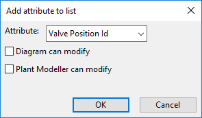
To add a new attribute to the tab, click Add. The Add attribute to list dialog opens for selecting an integration attribute and specifying its permissions.
-
To edit an attribute's permissions, select the attribute and click Edit.
-
To delete an attribute's permissions, select the attribute and click Delete. (Deleting the permissions allows both applications to modify the values.)
In the following example, the Edit Attributes dialog of Plant Modeller shows that the application can modify "Role in Process", but it cannot modify "Equipment Position Id".

Import settings tab
In the Diagram – Plant Modeller integration settings dialog, on the Import settings tab, you can specify mappings that are used when importing diagram (EPD) objects to Plant Modeller from an XML file. These mappings allow the imported objects to use appropriate attributes, object IDs, and catalog part mappings.
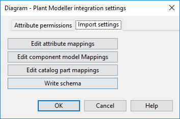
-
Edit attribute mappings – Opens a dialog where you can map an XML field to an integration attribute. When importing the XML file, the imported objects get their integration attribute value from this XML field.
-
Edit component model Mappings – Opens a dialog where you can map an XML field to a component model object ID (oid).
-
Edit catalog part mappings – Opens a dialog where you can map an XML field to a catalog part object ID.
-
Write schema – Opens a dialog for creating an XML schema file (EquipmentList.xsd, ValveList.xsd, InstrumentList.xsd, or DuctList.xsd) that allows Microsoft Excel to convert diagram object data to an XML format that Plant Modeller can import.

Using Microsoft Excel to create an XML file for diagram object import
Plant Modeller can import diagram objects from an XML file, and the file for such import can be created using Microsoft Excel.
Prerequisites
- Use the Write schema command described in Import settings tab to export an XML schema for each component type to be imported to Plant Modeller.
Do the following:
-
In Microsoft Excel, make sure the Developer tab is displayed in the ribbon. If it is not, right-click the ribbon, select Customize the Ribbon from the context menu, and then in the options dialog select the Developer main tab to be displayed.
-
Import the XML schema to the spreadsheet:
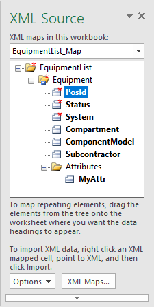
- On the Developer tab, click Source. The XML Source pane opens.
- In the XML Source pane, click XML Maps. The XML Maps dialog opens.
- In the XML Maps dialog, click Add, select the appropriate *.xsd schema file, and click Open. Then close the XML Maps dialog.
The imported schema is displayed as an XML map in the XML Source pane.
-
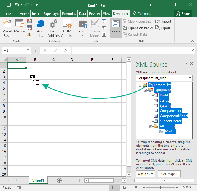
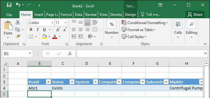
Drag the XML map from the XML Source pane to the worksheet to create an empty data table with predefined column names.
-
Populate the data table with the diagram object data that is to be imported to Plant Modeller.
-
Export the data table. On the Developer tab, click Export, and specify where to export the XML file.
Next, you can import the file to Plant Modeller, as described in Import from file (EPD).
